Overview
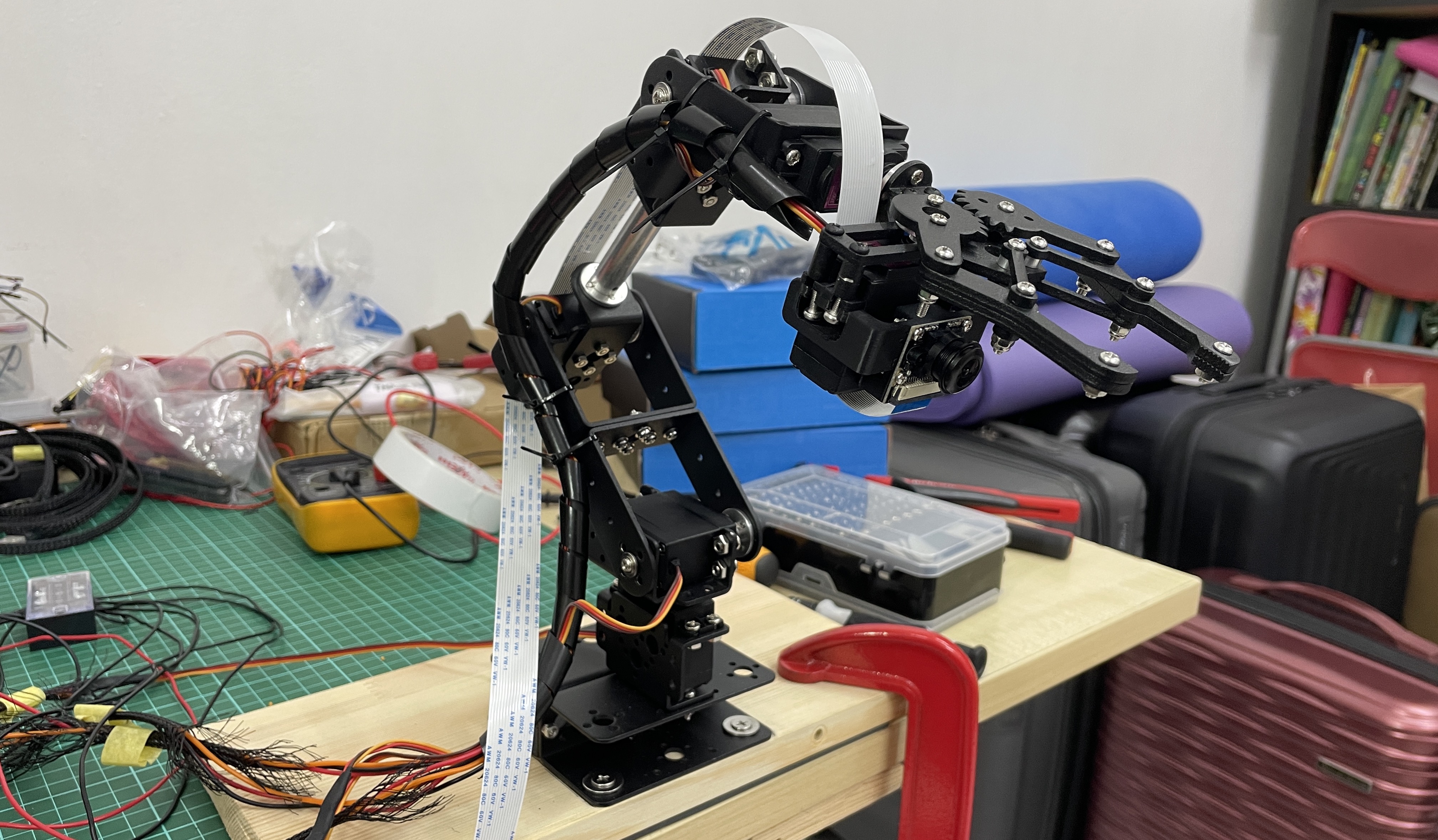
I built a robot arm with a camera attached to the end of it.
The arm is built with the aim of picking up and sorting colored blocks into corresponding boxes, but the project is currently unfinished, as I want to work on other projects. The mechanical, electrical and low level software part is mostly finished, leaving only the object recognition and block position estimation part left.

colored blocks
Mechanical
 The brackets, grippers, structural parts are all from a kit I bought from shopee. I also got 6 MG996R servos, and assembled the arm using this guide. (The guide is for another robot arm kit, but its quite similar to this one.)
where I drilled
There’s six servos, 1 servo is for rotation of base, 3 servos are for 3 planar arm joints, 1 servo is for rotating the gripper, and one is for controlling the gripper. Technically its capable of 5 DOF, but I didn’t utilise the servo for rotating the gripper, its only 4 DOF.
The servo horn of the base servo wobbles quite a bit, since the rest of the arm’s weight is being supported by it. Not too sure how to strengthen it tho.
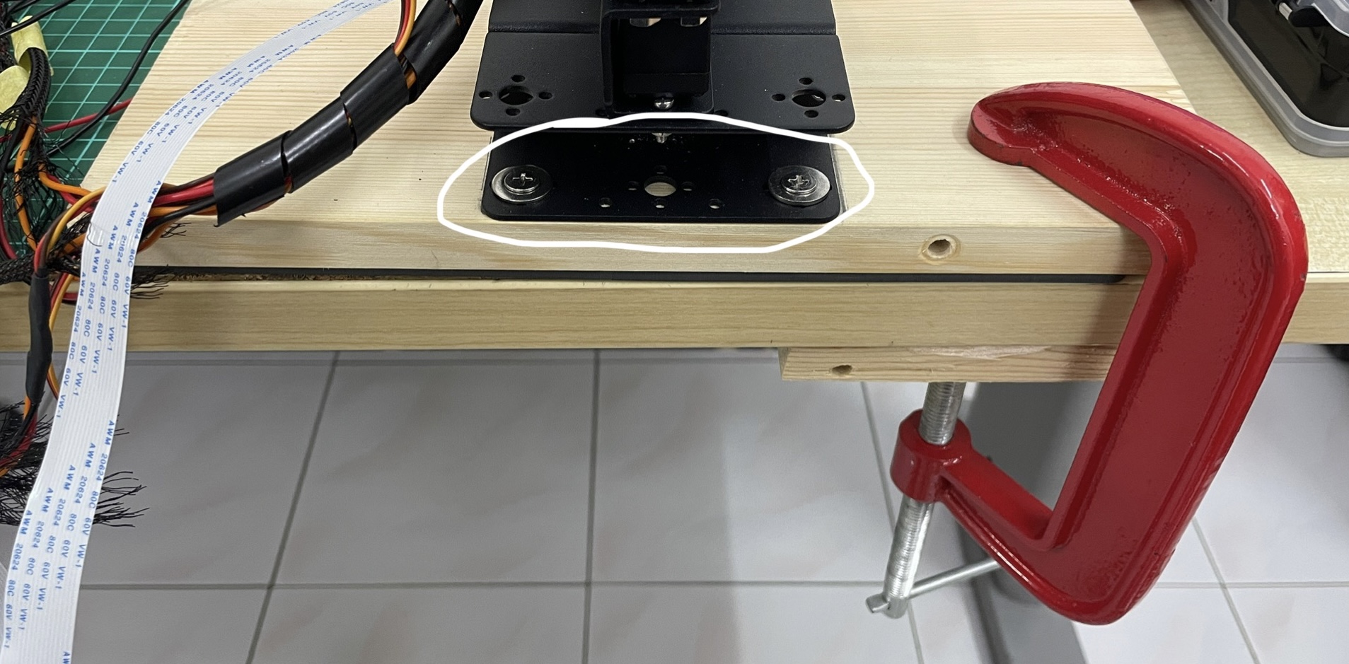
To hold the arm still on my table so that it wouldn’t jump around when its moving, I screwed its base to a piece of wood, and g clamped it to the table.
|
|
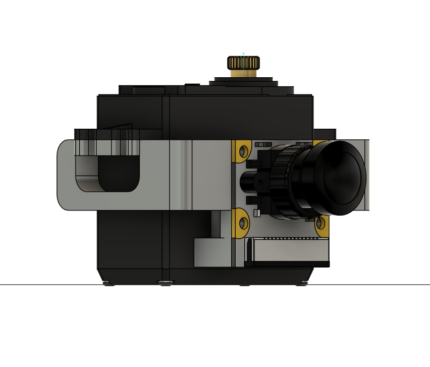
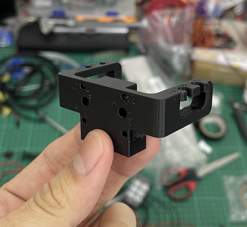
To attach the camera at the end of the arm, I designed a camera holder in Fusion and used a 3d printing service to print it out in PLA+.
Learned that I should always leave space in my design to actually fasten the screws, and leave more space for nuts, since it was difficult to install the arm-holder screws, and fasten the holder-camera nuts.
Electrical
|
|
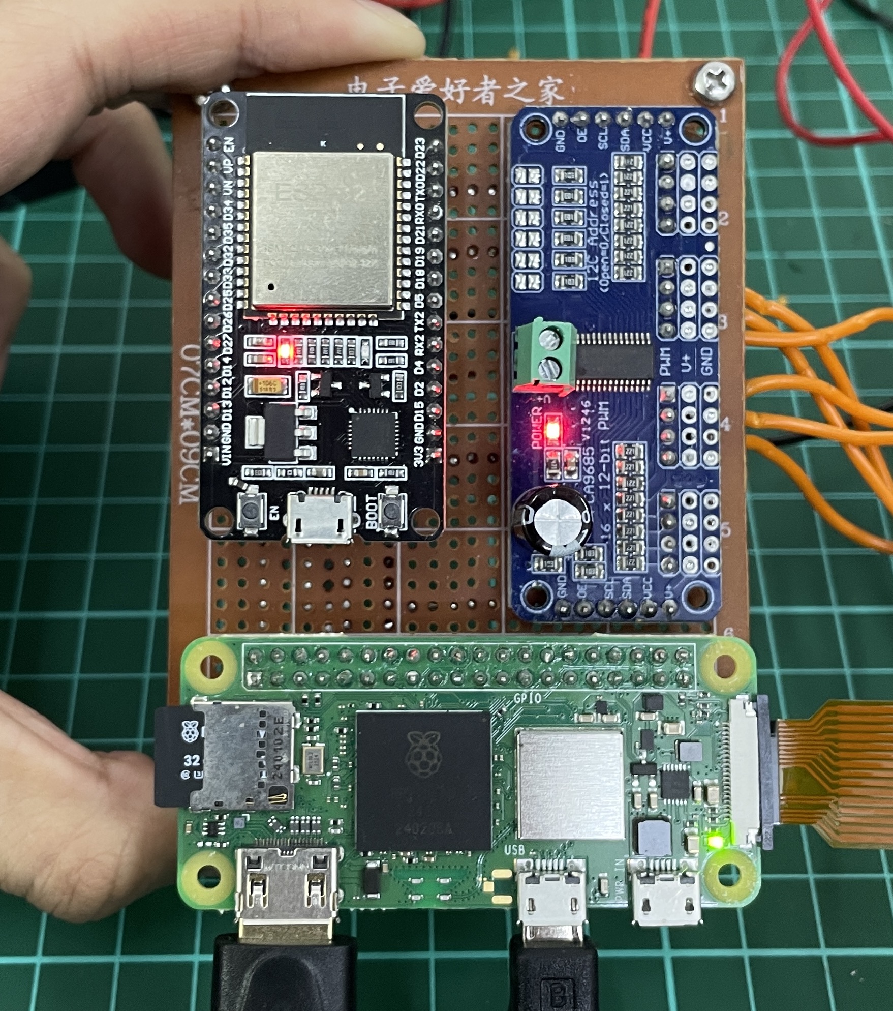
For controls, I used an ESP32, a PCA9685 servo driver, and a raspberry pi zero 2w.
The inverse kinematics code is in the ESP32, the servo driver is used to offload sending pwm signals, and the raspberry pi is used for the camera (and object recognition and approaching objects).
Might not have needed the ESP, but I think its nice to delegate off the inverse kinematics from the pi. Plus I wanted to learn to use ESP-IDF.
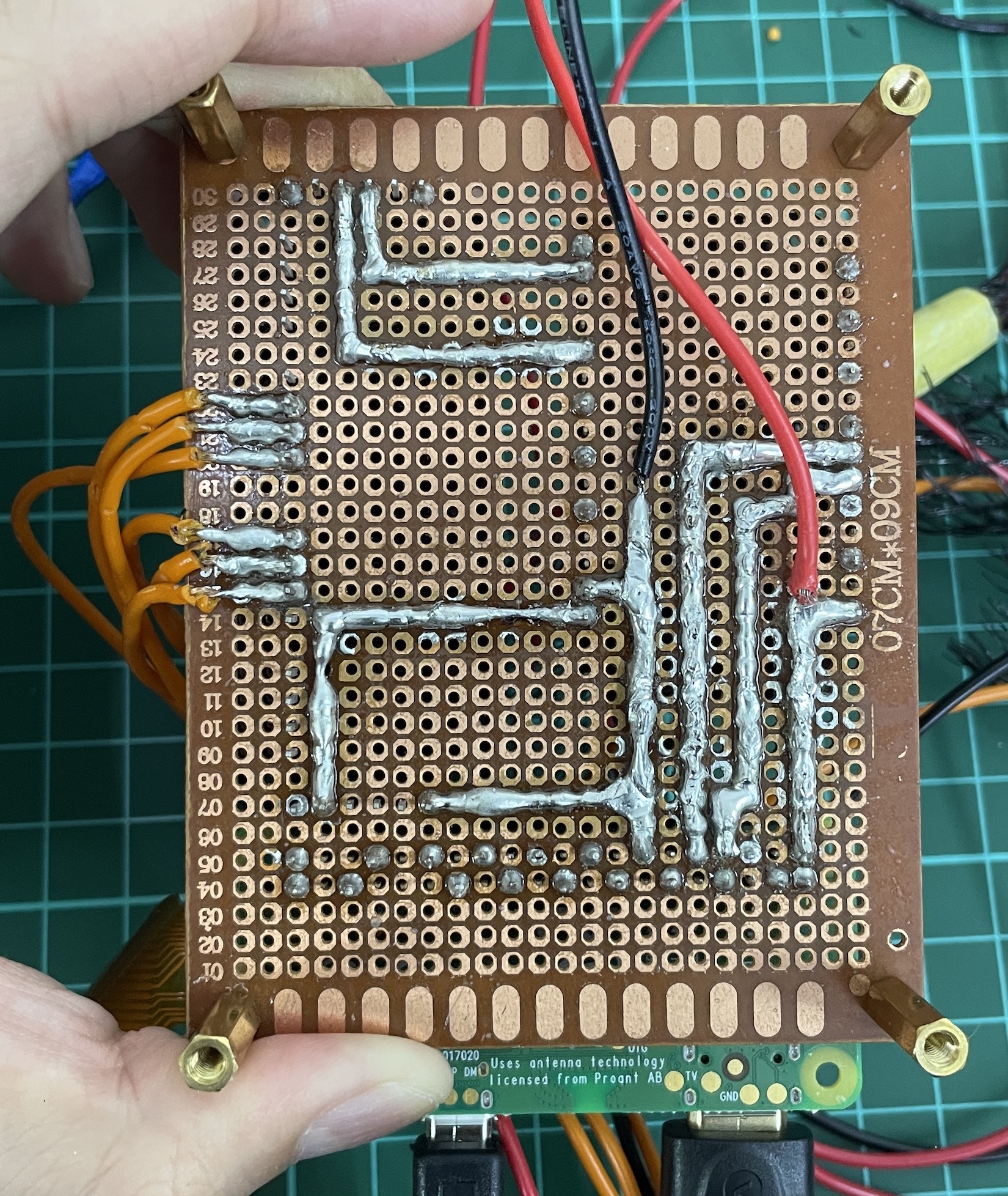
They’re all connected on a perfboard (my first ever perfboard!).
To connect the servo driver to the perfboard, I had to desolder the pins and resolder into the board. The ESP32 and pi is just plugged into soldered female pin headers on the perfboard.
The ESP32’s RX,TX lines are connected with the raspberry pi for UART, and the ESP32’s SCL,SDA lines are connected with the servo driver for I2C.

fisheye camera
I used a fisheye raspberry pi camera, so that it could have a wider view and detect more blocks. The camera is connected to the pi through a CSI ribbon cable.
The raspberry pi zero 2w’s CSI port accepted 22pins 0.5mm pitch, but the camera accepted 15pins 1mm pitch CSI ribbon cables, so to connect them you need 15pins to 22pins CSI ribbon cables. But here I faced a problem, there were just no 15pins to 22pins ribbon cables that were long enough for me (needed ~70cm). The only ones long enough were the 15pins to 15pins 1mm pitch ribbon cables.

ribbon cable extenders
I solved the problem by finding these nice little ribbon cable extenders. So now I could connect 22pins to 15pins cables from the pi to these extenders, and use a 15pins to 15pins cable to join the extender and the camera.
But there was another problem. The 15-22pin ribbon cables had exposed pins on the same side, but the 15-15pin ribbon cables had exposed pins on opposite sides. This meant that if I used this 15-15pin ribbon cable to connect to the extender and camera, I would have to twist the cable to connect to the camera, resulting in the pins being flipped. So pin #1 on the extender, would be connected to pin #15 on the camera.

self-made exposed pins
I solved the problem by exposing pins of the ribbon cable myself by following this youtube video, and scratching away the insulation using a utility/paper knife. The camera then worked.
Power

the electronics setup
As for the power supply, I used a 12V 200W PSU thats plugged into a wall socket, and connected it to a bunch of parallel XL4015 step down buck converters.
Each MG996R servos needed 6V and had a stall current of 2.5A, and the max output current for one XL4015 was 5A. So I connected 1 buck converter to 2 servos, and used 3 buck converters in total for 6 servos. Even if 2 servos connected to one buck converter stalled at the same time, it would still pull within the max output current of the buck converter. (probably not good to have no margin space/wiggle room,but oh well)
Afterwards, I actually found a step down buck converter which could handle outputting at 20A, which might be a better option. But the buck converter apartment I have looks pretty cool, plus idt there’s a part name/datasheet attached, so I’ll just stick with my current setup for now.
In the case that all the servos stalled (which probably won’t happen), the servos would pull a total of 90W, which is way below the PSU limit, even after accounting for power loss in the buck converter.
Why not use a 6V PSU, and straight connect to servos instead?
I remember that I didn’t really find any 6V PSU that could handle the power output I needed, but the convincing point for me was that I wanted the good line and load regulation by buck converters.
To power the pi and ESP32, I just connected 5V from another buck converter (so in total there’s 4 buck converters) to them:
5V -> VIN, GND -> common ground
The ESP32 devboard then converts the 5V to 3.3V, since the ESP32 board actually operates in 3.3v. Then to power the PCA9685 servo driver:
ESP32 3.3V -> PCA9685 VCC, PCA9685 GND -> common ground
The VCC of the servo driver has to match the logic level of the esp32, as the VCC is used for the 10K pull ups of the I2C. (ref)
The output voltage of the pi is also 3.3V, so its perfect for UART with ESP32. (since ESP32 can also only handle max 3.3V pin inputs.)
The total current load by the ESP32, Raspberry Pi, and also the PCA9685 servo driver is definetely under 5A, so the buck converter can totally handle it.
Wiring
All the wires connected are of the appropriate AWG (I think).
|
|
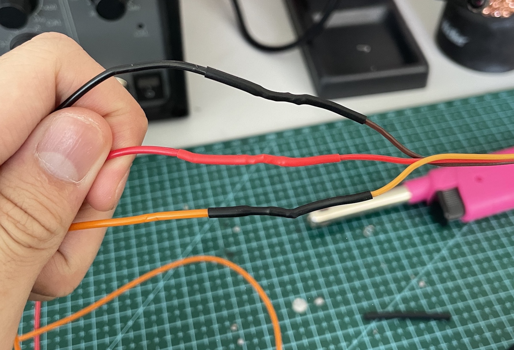
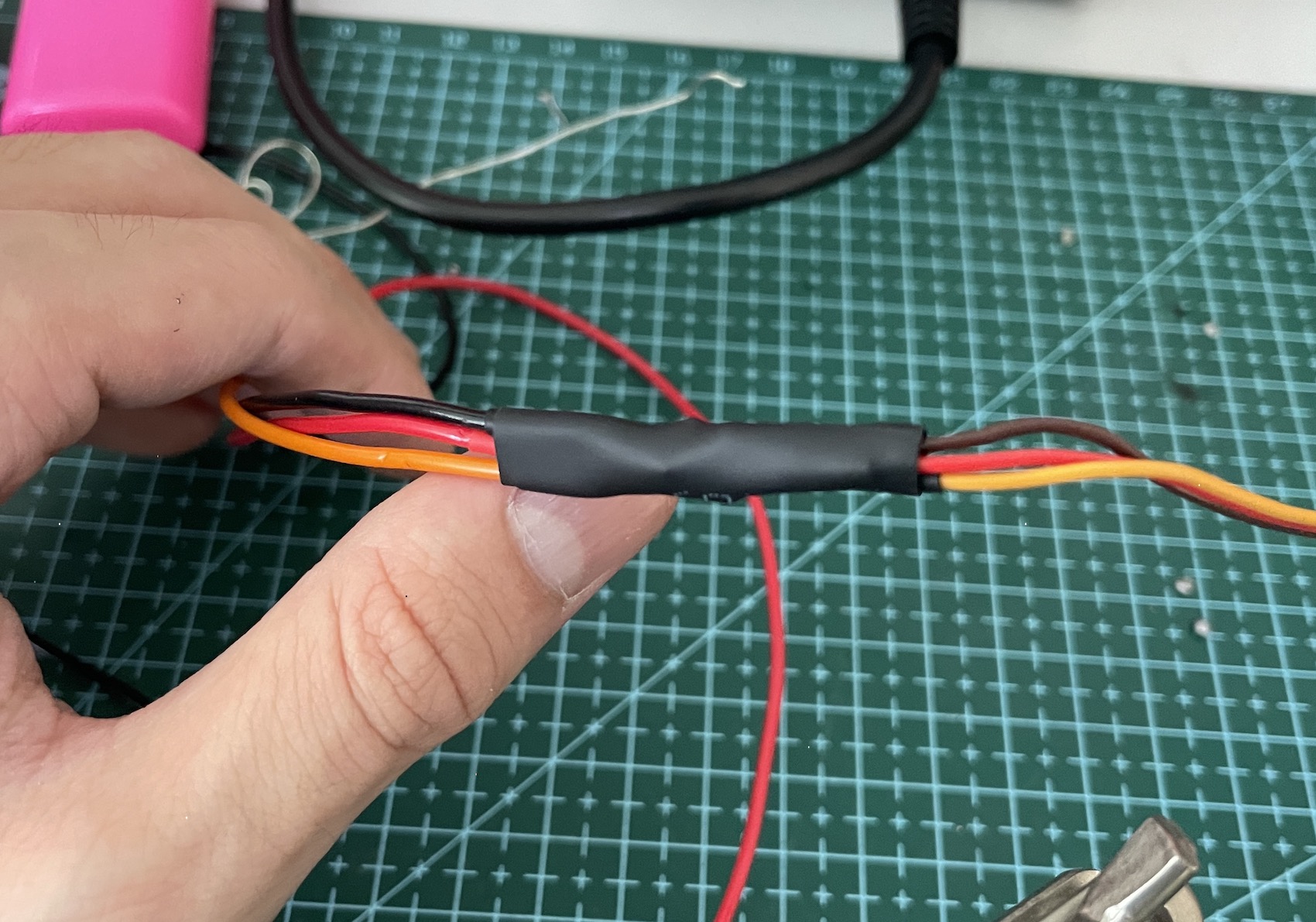
I stripped away the dupont female headers of the servo wires, and just soldered them to longer wires, that’s soldered to the perfboard / connected to buck converter or common ground.

cable management
For cable management, I inserted all the wires into a long spiral cable wrap that’s ziptied along the arm (so that it follows the arm no matter how the arm moves and won’t dangle and fly around). The camera ribbon cable is just duct taped to the servos.
All the other wire connections are made through either terminal blocks or soldered onto the perfboard.
Software
System overview
The pi runs two python scripts
- a web server that gives a GUI for controlling the robot arm
- a script that opens the camera (and was supposed to run object recognition).
When another computer connects to the web server and clicks a coordinate on the GUI, the raspberry pi talks to the ESP (through UART) to move to that coordinate. The ESP does some inverse kinematics, and calculates the joint angles. It then tells the servo driver (through I2C) what angles to turn to, and the driver will controls the servos through pwm signals. The arm then moves to the coordinate.
Its the same for turning the arm’s base and controlling the gripper, just without the IK.
The code for the project can be found here.
The ESP32’s software is written using ESP-IDF.
The chatbot on the esp-idf docs is really useful for finding how to do things and getting info.
Talking through UART
To setup UART2 on the ESP32:
    ESP_ERROR_CHECK(uart_driver_install(UART_NUM_2,0x2000,0x2000,0,0,0));
    uart_config_t uart_config = {
        .baud_rate = 115200,
        .data_bits = UART_DATA_8_BITS,
        .parity = UART_PARITY_DISABLE,
        .stop_bits = UART_STOP_BITS_1,
        .flow_ctrl = UART_HW_FLOWCTRL_DISABLE, // only tx,rx, no cts,rts
        .source_clk = UART_SCLK_DEFAULT,
    };

    ESP_ERROR_CHECK(uart_param_config(UART_NUM_2,&uart_config));
    ESP_ERROR_CHECK(uart_set_pin(UART_NUM_2,TX_PIN,RX_PIN,UART_PIN_NO_CHANGE,UART_PIN_NO_CHANGE));
And for reading and writing, I made some functions:
void uart_print(char* str){
    uart_write_bytes(UART_NUM_2,str,strlen(str));
}

char uart_getc(){
    // block main thread until read a byte
    size_t uart_buf_len = 0;
    while (uart_buf_len == 0)
        ESP_ERROR_CHECK(uart_get_buffered_data_len(UART_NUM_2,&uart_buf_len));

    // there is data to be read
    char c;
    uart_read_bytes(UART_NUM_2,&c,1,0);
    return c;
}

void uart_fgets(char *buf, int len) {
    // len includes the null byte
    int i;

    for (i = 0; i < (len-1); i++){
        char c = uart_getc();
        buf[i] = c;

        if (c == '\n') {
            i++;
            break;
        }
    }

    buf[i] = '\x00';
    return;
}

...

uart_print("...");
uart_fgets(...,30);
On the pi, I just used pyserial:
    ser = serial.Serial("/dev/serial0",115200,timeout=1)
    ...
    ser.read_until(b"...")
    ser.write(b"...")
Talking to Servo Driver through I2C
To setup I2C on the ESP32:
    // initialise esp32 as i2c master
    i2c_master_bus_config_t i2c_mst_config = {
        .scl_io_num = I2C_MASTER_SCL_IO,
        .sda_io_num = I2C_MASTER_SDA_IO,
        .i2c_port = I2C_NUM_0,
        .clk_source = I2C_CLK_SRC_DEFAULT,
        .glitch_ignore_cnt = 7,
        .flags.enable_internal_pullup = true,
    };

    ESP_ERROR_CHECK(i2c_new_master_bus(&i2c_mst_config,&bus_handle));


    // initialise pca9685 device
    i2c_device_config_t dev_cfg = {
        .device_address = 0x40,
        .dev_addr_length = I2C_ADDR_BIT_LEN_7,
        .scl_speed_hz = I2C_MASTER_FREQ_HZ,
    };

    ESP_ERROR_CHECK(i2c_master_bus_add_device(bus_handle,&dev_cfg,&dev_handle));
    ESP_LOGI(TAG,"I2C initialised succesfully");
Reading from the PCA9685 datasheet, as well as referencing Adafruit’s Arduino PCA9685 library source code, this is how I wrote the driver’s PRE_SCALE value and turned on auto increment for consecutive register writing:
// PRE_SCALE determines pwm output freq / frame size
// round(25MHz/(4096*50Hz)) - 1 = 121
#define PRESCALE_VAL 121
...
    // write PRESCALE (can only be written in sleep mode)
    uint8_t init_mode1 = read_reg(REG_MODE1) & ~MODE1_SLEEP;
    write_reg(REG_MODE1,init_mode1 | MODE1_SLEEP);
    write_reg(REG_PRESCALE,PRESCALE_VAL);
    write_reg(REG_MODE1,init_mode1);

    // turn on auto increment
    // have to wait 500 microseconds after awake from sleep before restarting
    delay(1);
    write_reg(REG_MODE1,init_mode1 | MODE1_AI | MODE1_RESTART);
    ESP_LOGI(TAG,"PRESCALE and AUTO_INCREMENT initialised");
To set the angle of a servo:
void set_angle(uint8_t id, double angle){
    if (angle > 178 || angle < 0){
        ESP_LOGE(TAG,"set_angle(), tried to set servo %d to angle %f",id,angle);
    }

    // map angle to pwm width
    double pwm_width = MIN_WIDTH + angle * ((MAX_WIDTH - MIN_WIDTH)/(double)SERVO_RANGE);
           pwm_width = round(pwm_width);
    uint16_t on = DELAY_PWM;
    uint16_t off = DELAY_PWM + (uint16_t)pwm_width;

    uint8_t buf[] = {REG_LED5 + 4*id, on & 0xff, on >> 8, off & 0xff, off >> 8};
    ESP_ERROR_CHECK(i2c_master_transmit(dev_handle,buf,5,-1));
}
I also wrote an update_servos function that takes in all the target servo angles, and smoothly turned the servos until it reached the target angles:
void update_servos(double target[6]){
    while (cur_angles[0] != target[0] || cur_angles[1] != target[1] || cur_angles[2] != target[2] ||
           cur_angles[3] != target[3] || cur_angles[4] != target[4] || cur_angles[5] != target[5]) {

        // turn all servos slowly at the same pace so that it looks smoother
        for (int i=0; i<6; i++){
            double diff = target[i] - cur_angles[i];
            if (diff == 0)
                continue;
            else if (diff > 0)
                cur_angles[i] += (diff > UPDATE_RATE) ? UPDATE_RATE : diff;
            else if (diff < 0)
                cur_angles[i] += (diff < -UPDATE_RATE) ? -UPDATE_RATE : diff;

            set_angle(i,cur_angles[i]);
        }

        delay(UPDATE_DELAY);
    }
}

// maybe I should just make target a global var
Inverse Kinematics
I treated the arm as a 3 DOF planar arm, that could rotate. Thus, I just had to solve 3 DOF inverse kinematics to move the end effector in a 2d plane, and rotate the arm to achieve 3d.
The idea is when the arm wanted to pick up a colored block, it could rotate so that it was looking directly at it first (and thus in the same plane as the block), then only reach for it.
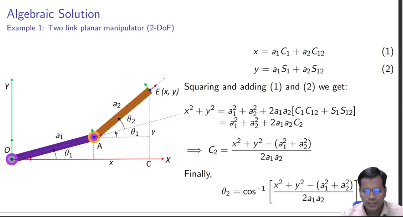
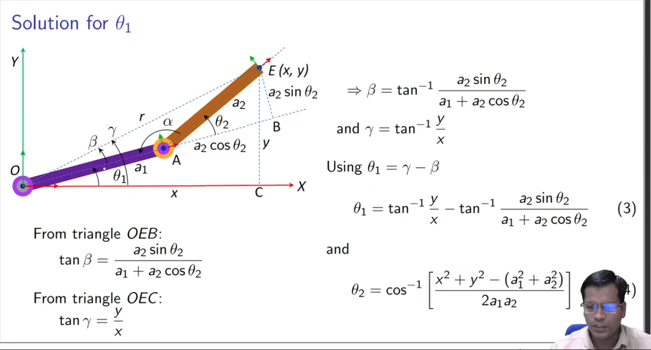
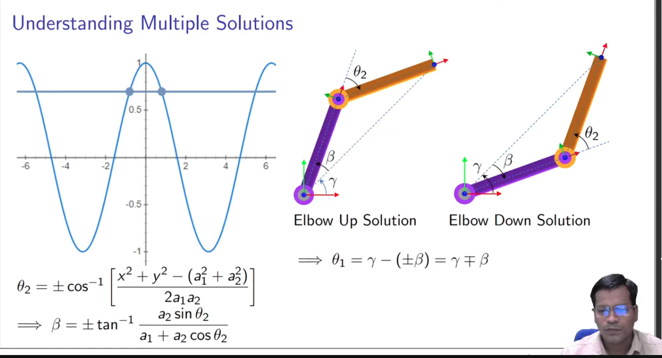
I learned the math by looking at the slides from this video. It talks about solving 2 DOF IK using geometry and algebra, and expanding it to solve 3 DOF IK.
Taking some screenshots from the video,
For 2 DOF:
C1 means cos(theta1), C12 means cos(theta1 + theta2)
For 3 DOF:
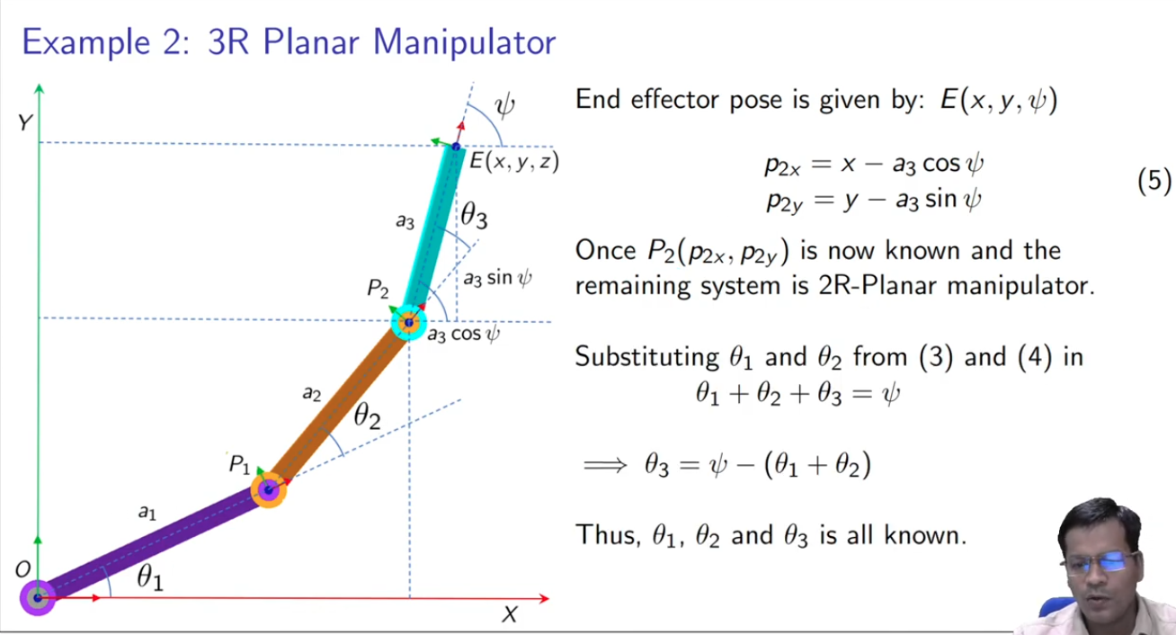
Still, I recommend going through the video and looking at the slides for more understanding.
My implementation in code:
expand
bool ik_solve(double target[3], double sol_1[3], double sol_2[3]){
    double x = target[0], y = target[1], psi = target[2];
    double theta1,theta2;

    // use 2R equations
    double p2x = x - A3*cos(DEG_TO_RAD(psi));
    double p2y = y - A3*sin(DEG_TO_RAD(psi));

    theta2 = acos((p2x*p2x + p2y*p2y - A1*A1 - A2*A2) / (2 * A1 * A2));

    //TODO figure out  the-x,-y
    if ((p2x < 0 && p2y < 0) || isnan(theta2)){
        return false;
    }

    // find 1st solution
    if (p2x >= 0)
        theta1 = atan(p2y/p2x) - atan( A2*sin(theta2) / (A1 + A2*cos(theta2)) );
    else
        theta1 = M_PI - atan(p2y/p2x) - atan( A2*sin(theta2) / (A1 + A2*cos(theta2)) );
    sol_1[0] = RAD_TO_DEG(theta1);
    sol_1[1] = RAD_TO_DEG(theta2);
    sol_1[2] = psi - sol_1[0] - sol_1[1];

    // find 2nd solution
    theta2 = -theta2;
    if (p2x >= 0)
        theta1 = atan(p2y/p2x) - atan( A2*sin(theta2) / (A1 + A2*cos(theta2)) );
    else
        theta1 = M_PI - atan(p2y/p2x) - atan( A2*sin(theta2) / (A1 + A2*cos(theta2)) );
    sol_2[0] = RAD_TO_DEG(theta1);
    sol_2[1] = RAD_TO_DEG(theta2);
    sol_2[2] = psi - sol_2[0] - sol_2[1];

    return true;
}

void convert_angles(double sol[3]){
    //TODO might need to do some stuff about looping angles, like % 360 etc
    // convert theoretical/irl angles into servo angles
    sol[0] = 90 + (EQB1 - sol[0]);
    sol[1] = 90 + (sol[1] - EQB2);
    sol[2] = 90 + (EQB3 - sol[2]);
}

bool choose_sol(double final_sol[3], double sol_1[3], double sol_2[3]){
    double score_1 = NAN;
    double score_2 = NAN;

    // TODO is there a better way to write this?
    // check if angles are in servo's range
    if (sol_1[0] <= SERVO_RANGE && sol_1[0] >= 0
     && sol_1[1] <= SERVO_RANGE && sol_1[1] >= 0
     && sol_1[2] <= SERVO_RANGE && sol_1[2] >= 0){
        // calculate score for sol_1
        score_1 = pow(cur_angles[1] - sol_1[0],2) + pow(cur_angles[2] - sol_1[1],2) + pow(cur_angles[3] - sol_1[2],2);
    }

    if (sol_2[0] <= SERVO_RANGE && sol_2[0] >= 0
     && sol_2[1] <= SERVO_RANGE && sol_2[1] >= 0
     && sol_2[2] <= SERVO_RANGE && sol_2[2] >= 0){
        score_2 = pow(cur_angles[1] - sol_2[0],2) + pow(cur_angles[2] - sol_2[1],2) + pow(cur_angles[3] - sol_2[2],2);
    }

    if (isnan(score_1) && isnan(score_2)){
        return false;
    }

    if (isnan(score_1))
        memcpy(final_sol,sol_2,sizeof(double)*3); // must use sol_2
    else if(isnan(score_2))
        memcpy(final_sol,sol_1,sizeof(double)*3); // must use sol_1
    else if (score_1 > score_2)
        memcpy(final_sol,sol_2,sizeof(double)*3); // sol_2 less change
    else if (score_1 <= score_2)
        memcpy(final_sol,sol_1,sizeof(double)*3); // sol_1 less change or equal amount of change

    return true;
}
When the second joint is in (-,+), the formula for theta1 is slightly different. The math when second joint is in (+,-) is the same tho. Not too sure on (-,-).
One of the problems I faced is that there had to be a third argument psi (the orientation of the gripper) in order to solve the IK, and not just x,y. I wanted the GUI to just control the x,y coordinates and dont worry about the psi value, so I dealt with this by just trying a bunch of psi values for each x,y:
                bool is_successful = false;
                for (double psi=-180; psi <= 180; psi += 15) {
                    coords[2] = psi;
                    double sol_1[3] = {0,0,0};
                    double sol_2[3] = {0,0,0};

                    if (!ik_solve(coords,sol_1,sol_2))
                        continue;


                    convert_angles(sol_1);
                    convert_angles(sol_2);

                    double final_sol[3] = {0,0,0};
                    if (!choose_sol(final_sol,sol_1,sol_2))
                        continue;

                    memcpy(&target_angles[1],final_sol,sizeof(double)*3);
                    update_servos(target_angles);
                    is_successful = true;
                    break;
                }

// there's probably better ways to deal with this
Forward Kinematics
Compared to inverse kinematics, planar forward kinematics is simpler, and is just some trigonometry:
forward kinematics math
I wrote some code to help check if solutions from my inverse kinematics code was correct:
import math

cos = lambda degrees: math.cos(math.radians(degrees))
sin = lambda degrees: math.sin(math.radians(degrees))

# link lengths (cm)
a1 = 10.5
a2 = 12.4
a3 = 18.2

# theoretical angles (degrees)
theta1 = ...
theta2 = ...
theta3 = ...


x = a1*cos(theta1) + a2*cos(theta1+theta2) + a3*cos(theta1+theta2+theta3)
y = a1*sin(theta1) + a2*sin(theta1+theta2) + a3*sin(theta1+theta2+theta3)
psi = theta1 + theta2 + theta3

print("x: {}, y: {}, psi: {}".format(x,y,psi))
Exploring configurations
In my project, theoretical / irl angles means the angle from the horizontal. theoretical angles
Anticlockwise is positive, and clockwise is negative:

This follows the IK math.
Actual servo angles are the angles written to the servos. So depending on how you screw in the arm links to the servo horns, different servo angles correspond to different theoretical angles. I call these different configurations.
Through my own measurements (using a protractor and a pen, not the most accurate), I found that the MG996R servo can move from angles 0 - 178. When the servo angle is 90 degrees, I like to say that the servo is in equilibrium position.
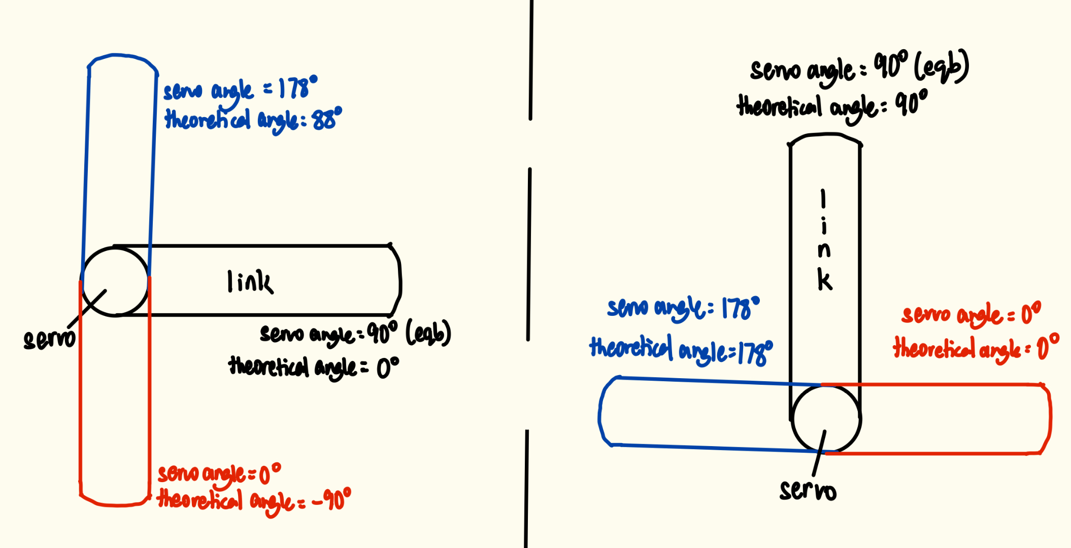
different configurations for one servo/joint
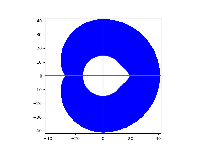
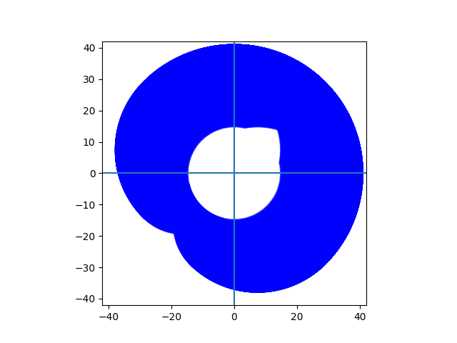
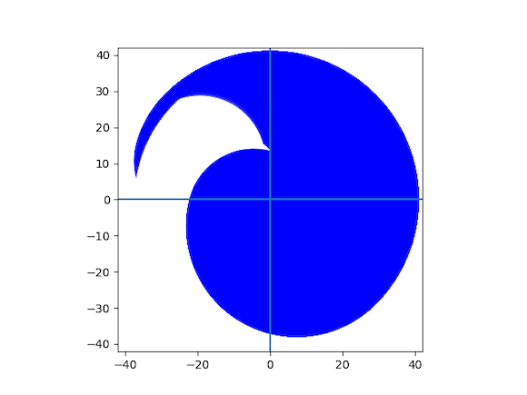
So depending on different configurations for all 3 joints, the reachable workspace is different.
I used forward kinematics and wrote some code to visualise the reachable workspace of different configurations, to help me choose which configuration to use:
import matplotlib.pyplot as plt
from matplotlib.patches import Arc
import math

cos = lambda degrees: math.cos(math.radians(degrees))
sin = lambda degrees: math.sin(math.radians(degrees))

# link lengths (cm)
a1 = 10.5
a2 = 12.4
a3 = 18.2

fig, ax = plt.subplots()

# eqb1 means the theoretical angle of first joint, when first servo is in equilibrium position
def draw(eqb1,eqb2,eqb3):
    for theta1 in range(eqb1-90,eqb1+90+1):
        for theta2 in range(eqb2-90,eqb2+90+1):
            # coordinates of joint 2
            p2x = a1*cos(theta1) + a2*cos(theta1+theta2)
            p2y = a1*sin(theta1) + a2*sin(theta1+theta2)

            arc = Arc(xy=(p2x,p2y),width=2*a3,height=2*a3,
                      angle=theta1+theta2,theta1=eqb3-90,theta2=eqb3+90,
                      edgecolor="blue",lw=0.5)
            ax.add_patch(arc)
            #plt.plot(p2x,p2y,"ro")

            print("theta1: {}, theta2: {}".format(theta1,theta2))


draw(...,...,...)

full_radius = a1+a2+a3
ax.set_aspect('equal')
ax.set_xlim(-50, 50)
ax.set_ylim(-50, 50)
ax.axhline(0)
ax.axvline(0)

plt.show()
Some examples:
| (0,0,0) | (45,0,0) | (45,-60,-60) |
|---|---|---|
|
|
|
(45,0,0), means that for servo1, it is at eqb position when theoretical angle = 45. For servo 2 and 3, they are at eqb position when theoretical angle = 0
The coordinate (0,0) is at servo 1’s servo horn.
Some configs might look good, but might result in collisions with the table or arm itself (physical limitations).
Currently the config being used is (45,0,0).
GUI and Server
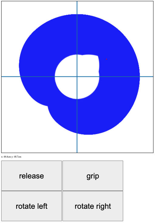
GUI
I used the reachable workspace visualisation and put in on a html canvas.
Everytime you click on the canvas, the coordinate will be sent through POST to the server.
    var resp = await fetch("http://" + ip + ":5000/move", {
        method: "POST",
        body: JSON.stringify({x: x, y :y}),
        headers: {"Content-type": "application/json; charset=UTF-8"}
    });
The red dot on the canvas represents where the end effector is currently (sometimes it works, sometimes it doesn’t).
Once the server gets the POST request, it will send a command to the ESP through serial/UART:
@app.route("/move",methods=["POST"])
def move():
    try:
        msg = str(request.json["x"]) + "," + str(request.json["y"]) + "\n"

        ser.read_until(b"choice:")
        ser.write(b"0\n")
        ser.read_until(b"x,y:")
        ser.write(msg.encode())

        ser.read_until(b"success: ")
        if(ser.read(1) == b"1"):
            return {"success": True},200
        else:
            return {"success":False},200

    except Exception as e:
        app.logger.warning("ESP not connected")
        print(e)

        return {"success":False},200
This is a good time to mention that the ESP32 is actually running a menu service (like pwn challs):
    while (true){
        // 1: move 2: control gripper 3: rotate base
        char choice_str[10] = "";
        uart_print("choice:\n");
        uart_fgets(choice_str,10);
        int choice = atoi(choice_str);

        ...

        switch (choice) {
            case 0:
                // move end effector
                ...

            case 1:
                // control gripper
                ...

            case 2:
                // rotate base
                ...

            default:
                uart_print("no such choice\n");
                break;

        }
    }
The server actually first sends the command code, then sends the info necessary to execute the commands.
So after the server sends the coordinates to the ESP32, the ESP32 will execute the command by telling the servo driver to move the servos. The ESP32 will also tell the server whether the command was successful or not. The process for controlling gripper and rotating base is similar.
When you first power on everything, the ESP32 will of course boot up much quicker than the pi, so by the time server.py runs on the pi, and the pi starts listening on the serial connection, it won’t catch the initial string “choice:” from the esp32. So to solve this, just:
ser.write(b"5\n")
ser.read_until(b"no such choice\n") # load b"choice:" in the RX pyserial buf
send an invalid command and get a response at the start of server.py. That way the “choice:” strings sent afterwards are actually listened and stored in the serial buffer.
Object recognition
To just open the camera connected to the pi:
import cv2 as cv
import numpy as np
from picamera2 import Picamera2

cam = Picamera2()
cam.start()

while True:
    frame = cam.capture_array()
    if frame is None:
        print("no frame captured")
        break

    frame = cv.cvtColor(frame,cv.COLOR_RGB2BGR)

    # constantly show new frame
    cv.imshow("frame",frame)
    if cv.waitKey(1) == ord("q"):
        break

cv.destroyAllWindows()
I also worked on the object recognition part a bit, on my laptop:
import cv2 as cv
import numpy as np

cap = cv.VideoCapture(0)
if not cap.isOpened():
    print("Cannot open camera")
    exit()

while True:
    ret, frame = cap.read()

    if not ret:
        print("no frame read")
        break


    img = cv.cvtColor(frame,cv.COLOR_BGR2HSV)

    # mask colors
    mask1 = cv.inRange(img,(0,100,50),(5,255,255))
    mask2 = cv.inRange(img,(175,100,50),(179,255,255))
    img = cv.bitwise_or(mask1,mask2)

    # opening
    kernel = np.ones((3,3),np.uint8)
    img = cv.morphologyEx(img,cv.MORPH_OPEN,kernel)

    # find and draw contours
    contours,hierarchy = cv.findContours(img,cv.RETR_TREE,cv.CHAIN_APPROX_SIMPLE)
    if contours:
        c = max(contours,key=cv.contourArea)
        peri = cv.arcLength(c,True)
        approx = cv.approxPolyDP(c,0.015*peri,True)
        if len(approx) < 9:
            cv.drawContours(frame,[approx],-1,(0,0,150),3) # frame still in bgr form

    # constantly show new frame
    cv.imshow("frame",frame)
    if cv.waitKey(1) == ord("q"):
        break

cap.release()
cv.destroyAllWindows()
I just did some masking, morphological operations, countours finding, and contour approximation.
It doesn’t work too well when a bunch of blocks are near each other since it’ll form a big contour, but I think this can be solved by moving the arm over the blocks and having a top down view.
For this to work on the fisheye camera, I’ll prob have to put a filter since the frames from the fisheye camera are more reddish, and then adjust the values for the mask.
To finish this project, I’ll have to implement a way to find distance (maybe focal length method), then do some math to estimate where the block is on the plane, and slowly move towards the block. I also have to implement the object recognition for blue and green blocks, as well as recognising the boxes to put the blocks into. Also, I have to write the logic for scanning/choosing which blocks to go for first.
Conclusion
I learned a huge ton from this project, and had a lot of fun. Don’t hesitate to tell me what improvements I can make to it. Maybe I’ll finish it some day.